Mechanical Dragster
Description
A dragster is a car which has to go as fast as possible on a defined distance. It is usually gas powered and has a lot of hors power to be able to break records.
In our case, we had to make a 35cm long dragster only powered by mechanical energy. This means no fuel and no electricity allowed. This constraint makes the hole project really interesting to work on since we had to find another way of energy storage, such as rubber bands, springs, compressed air…
Context
I’m studying mechanics and production at the university of Mulhouse and in the last year we had to do a project. This year, the project was inspired by a competition called “Course en Cours”. This competition consists by creating a dragster and all the competitors race each other and the fastest wins. The race tracks are usually 15 meters long and the speed is measured thanks to sensors at the start and the end of the track.
The teachers allowed us to use all the machines and raw materials present in our school’s workshop except for wood since its not easy to machine. The workshop is really big, we have 6 numerical milling machines, 2 numerical lathes and a lot of conventional lathes and milling machines.
This work was made in groups of 3 so I was with two other colleagues of my promotion and we had almost 200 hours to create this dragster.
Steps
Choose the best idea
As we were three, we had three different ideas. So first we had to choose the best idea following the next criteria:
- Most interesting mechanism
- Most efficient mechanism
- Easiest to machine and assemble
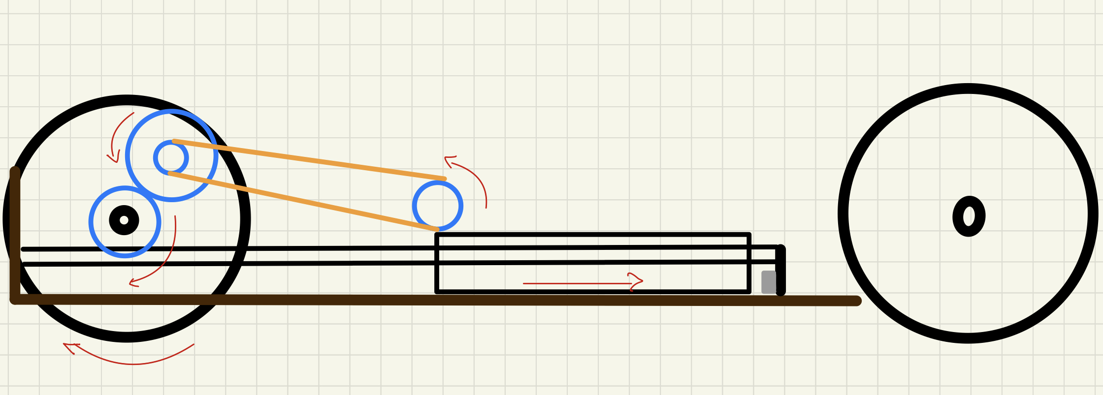
At this point, this was our idea:
Once we decided the mechanism we wanted to create, it was time to proceed to the next step, the theoretical approach.
Theoretical approach
We had first to doo the cinematic graph. It represents all the links of the mechanism (pivots, gears, slides…):

In this graph, we can see that the idea is to store energy in springs and use a gear rack and a gear to transform the linear motion into a rotation motion.
But what size of gear rack should we go with?
To answer this question, we did some maths knowing that the maximum size of the vehicle can not exceed 350 by 130 by 150mm. The wheels are also given by the teachers and their diameter is 65mm.

Conception
We now know that the vehicle can not exceed a defined size, we also know the size of the gear rack and the wheels so it was time to do the rest of the conception. In school we use a different CAD software than I usually use, which is CREO 6. This software is commonly used in the industry and it’s a really powerful tool.
I wanted to make the vehicle as light as possible but sturdy enough to not break apart. To be able to make it light, I privileged plastic and aluminium over steel, so we used mainly 3D printed and laser cut parts. However, some technical parts which had to be strong were machined on CN machines.
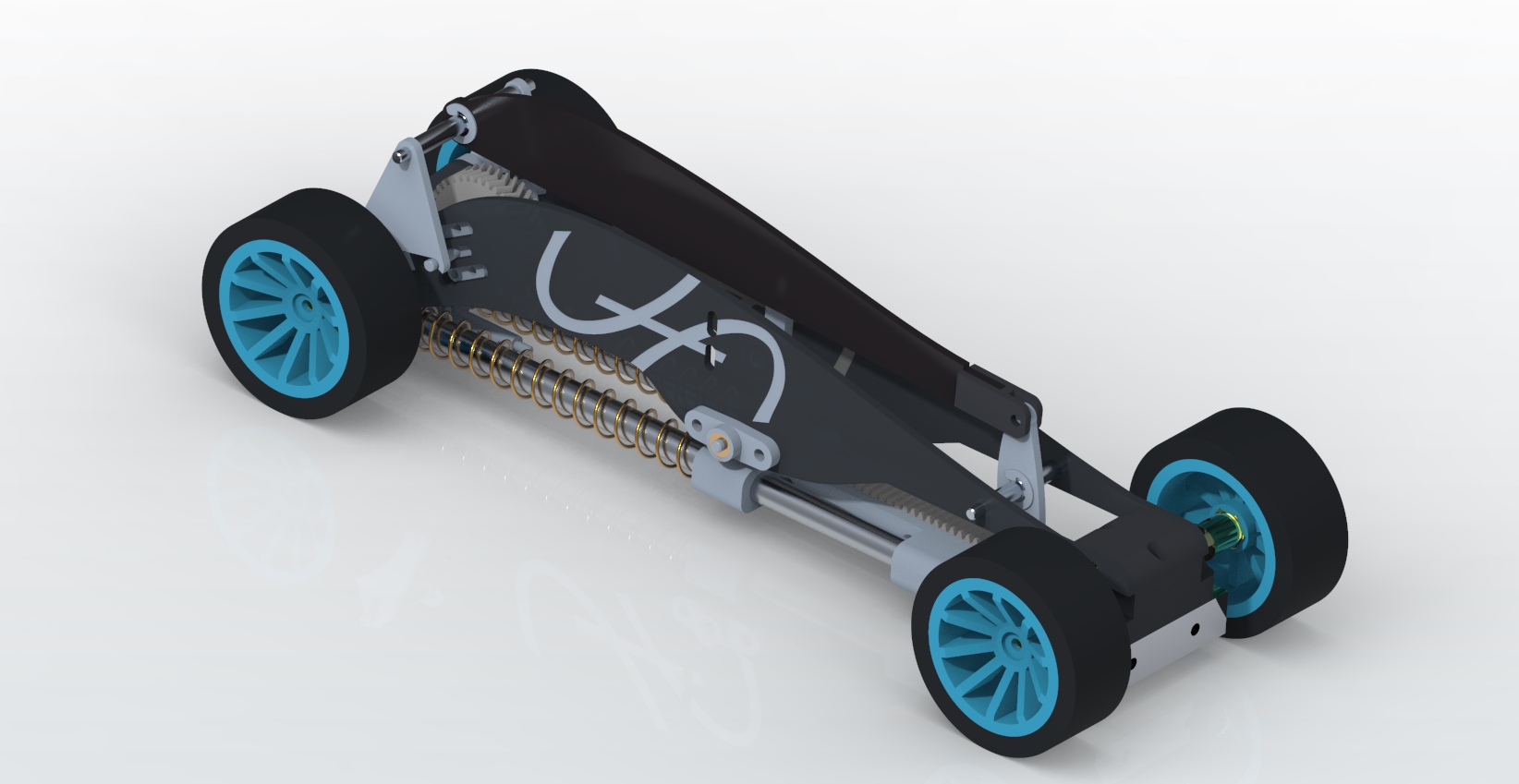
Here are some pictures of our finished conception:
While creating the parts we had to keep in mind the esthetical aspect since it’s a point that the teachers will mark.
An interesting feature that CREO has is that in the assembly we can animate the components. In our assembly we have a succession of gears and pulleys that we animated so when we push the gear rack with the mouse, it makes the hole mechanism work:
The dragster’s conception was the most time-consuming part of the hole process. But once it was done, we had the hardest part behind us and it was time to go on to the fabrication of all our parts.
Fabrication
As I said it before, we manly used 3D printed parts. This was really convenient since 3D printers are autonomous machines which can run days on their own without requiring any human intervention. The only down side is that they take a long time to finish the part. But in the meantime, we could laser cut some other parts of the vehicle.
We also had some interesting parts to machine out of aluminium thanks to CNC mills and lathes. But before machining parts on a CNC machine, we have to crate a program (G-code) that the machine can understand. To create these programmes, we used a software called ESPRIT. This software is compatible with almost all the CNC machines, lathes or milling machines. In this software, we basically define the toolpaths, the type of tools that we are going to use and also the feed and rotary speeds.
Here is a video of the simulation which is created by ESPRIT:
However, we also had to mill several parts on conventional machines, here are some videos of the process:
Once all the parts were machines or 3D printed, we still had to buy some mechanical components such as bearings, screws, springs, belts and so on… But when these components arrived, we could start the assembly.
Assembly
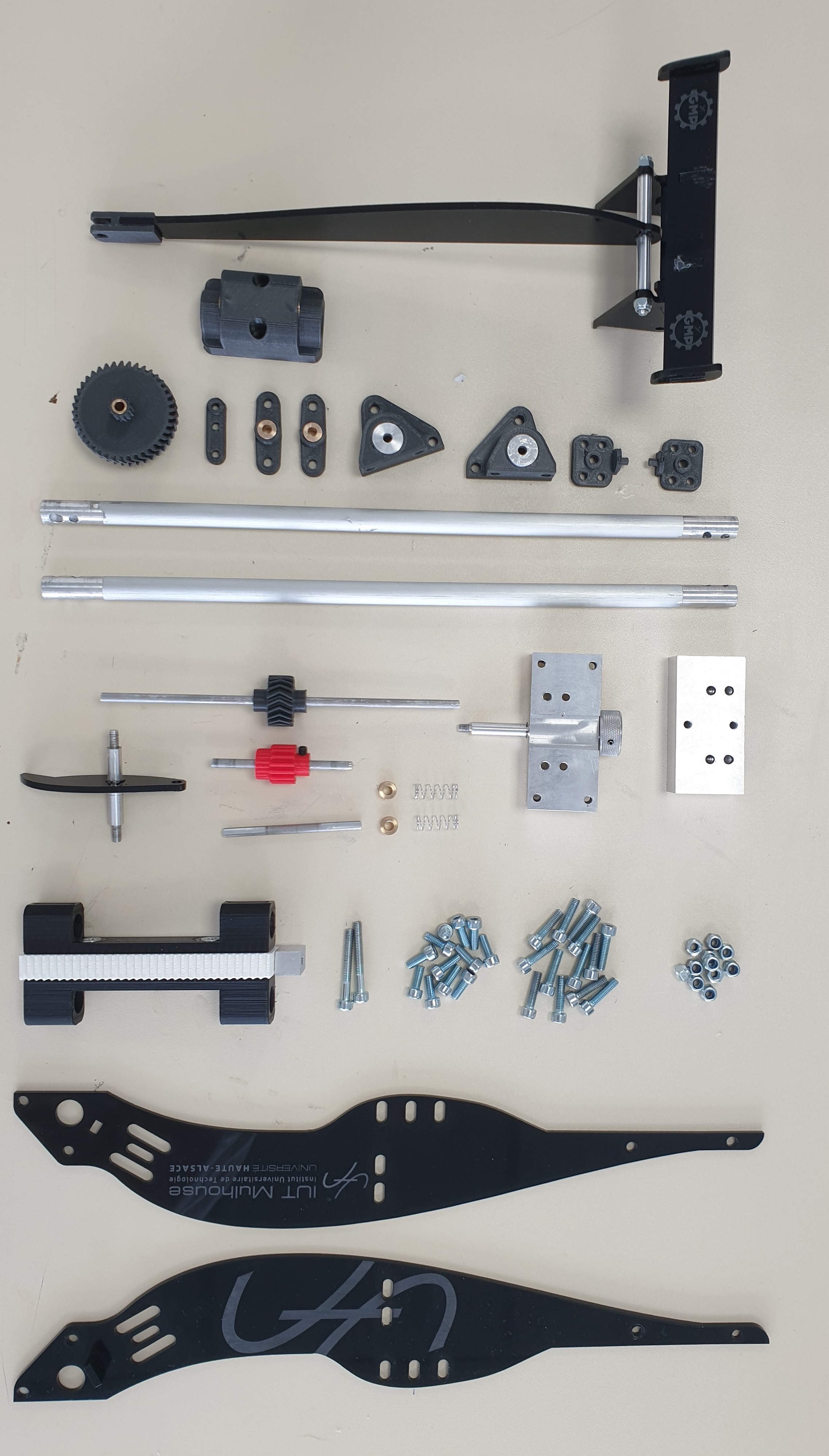
The assembly process was really exiting since, it’s the moment we can see all the parts coming together and create the final vehicle. It went quite fast because we didn’t run into many issues. However, we had to reprint two parts because they were not fitting in the assembly. But a few hours of printing later, we were able to complete the final assembly.
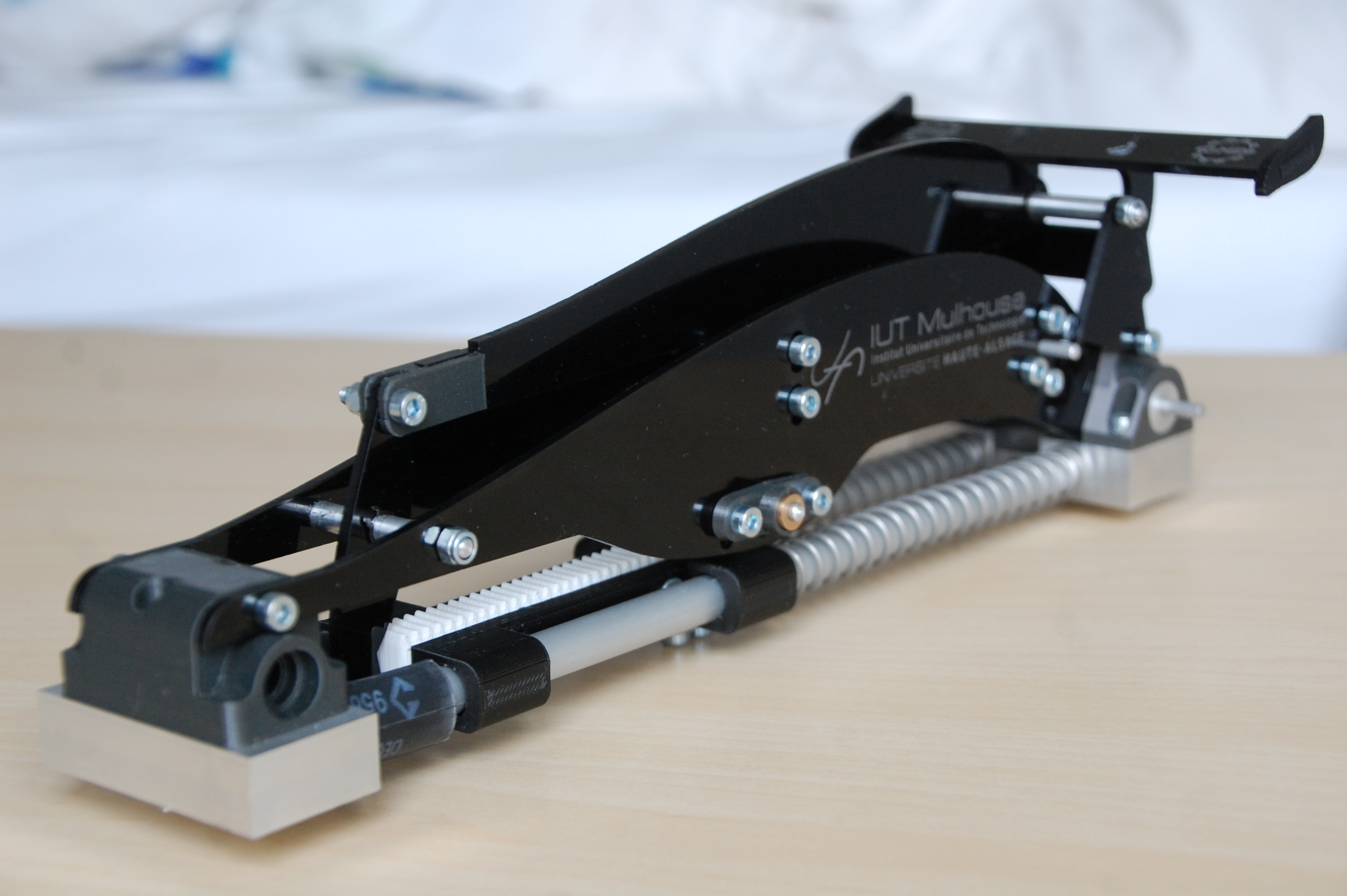
The final product
Once the final assembly completed, the only thing left to doo was to test if indeed the dragster works. The only issue was that the parts didn’t came fast enough so we didn’t had bearing neither wheel. So, we had to find another way to make the vehicle work.
We had to quickly machine four plain bearings to use them instead of the bearings.
Here is a pictures of the assembled vehicle. The test are going to made in a short time...